The Rainbow Film That Wasn’t a Failure
A sputtered zinc oxide film was expected to be uniform. Its unexpected colors revealed hidden differences in structure, composition, electrical behavior, and gas-sensing performance across a single glass slide.
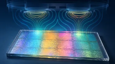
The zinc oxide film was supposed to look the same from one edge to the other.
It did not.
When I removed the five-centimetre glass slide from the sputtering chamber and tilted it towards the light, blue, pink, gold, and green bands moved across its surface. It looked more like a soap bubble than a carefully deposited scientific coating.
My first thought was not discovery.
It was: Something went wrong.
Perhaps the chamber was contaminated. Perhaps the vacuum was poor. Perhaps I had made a mistake while preparing the sample. I repeated the deposition without changing the power, pressure, gas flow, or distance.
The colours returned.
I repeated it again. The same pattern appeared in almost the same places.
A random mistake should not reproduce itself so faithfully. That was when the “failed” film became a scientific question.
A defect that returns in the same place may not be noise. It may be evidence of a variable we have overlooked.
Why we wanted a uniform film
We were not trying to make a colourful coating. We were trying to improve a gas sensor.
In an earlier experiment, our group had deposited zinc oxide—ZnO—through a stencil to produce a grid of small squares. When the ZnO encountered a gas, its electrical resistance changed. The patterned grid also interacted with radio waves, so the electrical change shifted the frequency at which the device responded.
This type of patterned structure is called a frequency-selective surface, or FSS. In simple terms, it acts like a filter that responds differently to selected radio frequencies.
The idea worked, but the ZnO coating produced by spray pyrolysis was visibly uneven. We therefore turned to radio-frequency magnetron sputtering, a vacuum-coating method that offers good control over deposition conditions and reproducibility.
We expected a more uniform film.
Instead, sputtering gave us a different kind of unevenness—one that appeared to be built into the deposition geometry itself.
The first clue was colour
The colours were not pigments, and the ZnO had not somehow turned blue, pink, or gold.
They came from thin-film interference.
Light reflected from both the upper surface of the ZnO coating and the boundary beneath it. Depending on the film’s thickness and optical properties, some wavelengths reinforced one another while others cancelled out. The same effect produces shifting colours in soap bubbles and thin oil films.
On our sample, the changing colours were therefore more than a visual curiosity. They suggested that the film was not identical everywhere.
The repeated colour pattern told us that the cause was systematic. But what inside a controlled vacuum process could create such a strong spatial pattern?
To answer that, I stopped looking only at the film and began looking more closely at the chamber.
The hidden racetrack inside the sputtering chamber
In magnetron sputtering, a plasma bombards a solid target and ejects atoms from its surface. Those atoms travel through the chamber and settle on a substrate, gradually forming a thin film.
Magnets behind the target help trap electrons near its surface. The electrons follow a ring-shaped path and intensify the plasma above that ring. As a result, the target erodes fastest along a circular zone known as the racetrack.
The magnetic field is not equally strong at every point above the target. In our system, it was close to 700 gauss over parts of the racetrack but fell below 250 gauss away from it.
Our stationary glass substrate extended across regions influenced differently by this magnetic and plasma environment. Its centre, intermediate areas, and outer regions did not necessarily receive arriving particles under identical local conditions.
Sputtering is often selected because it provides tighter process control than many solution-based coating methods. But controlling the overall process does not guarantee identical growth at every position on a large, stationary substrate.

The racetrack gave us a plausible cause. We still needed to determine whether the visible bands represented only an optical effect or deeper changes in the material.
One film became five samples
We divided the continuous ZnO film into five spatial regions and examined them separately.
The measurements confirmed that the colour bands were marking real material differences:
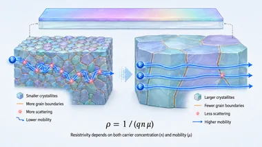
- The average ZnO crystallite size increased from approximately 11 to 35 nanometres across the sampled regions.
- The balance between zinc and oxygen changed substantially with position.
- The strain within the crystal lattice varied; one intermediate region came closest to strain-free bulk ZnO.
- The optical band gap and electrical carrier behaviour were also position-dependent.
These were not merely cosmetic variations. The location of a region on the glass influenced how the ZnO grew, how its crystal structure developed, and how electrical charge moved through it.
One deposition had produced five measurably different regions—almost as though we had prepared several samples under different conditions.
| What changed? | Why it mattered |
|---|---|
| Crystallite size | Revealed differences in how the ZnO crystals grew |
| Zinc-to-oxygen balance | Indicated position-dependent composition and defects |
| Lattice strain | Showed that the crystal structure was not equally relaxed everywhere |
| Carrier behaviour | Affected how readily electrical charge moved through the film |
| Optical band gap | Confirmed that the electronic structure varied across the coating |
Yet structural differences alone did not tell us whether the spatial variation would affect the film’s practical function. The decisive test was to use each region as a sensor.
The sensor test changed the meaning of the film
We converted the five regions into separate ethanol sensors and exposed them to the same concentration: 100 parts per million at room temperature.
Their responses were dramatically different.
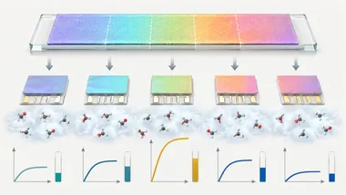
One region produced a response of approximately 4.6, several times stronger than nearby regions cut from the same glass slide. It also recovered in less than a minute.
The result changed the meaning of the rainbow pattern. It was no longer simply evidence that the coating thickness or appearance varied. It showed that position could alter what the material actually did.
This has an important consequence for experimental reproducibility. Two researchers could cut devices from different positions on the same apparently continuous film and report substantially different sensor performance. Both measurements might be correct. The missing experimental variable would be where each device came from.
“Prepared under the same conditions” does not always mean “experienced the same local growth environment.”
For large-area thin films, sample position may need to be recorded with the same care as deposition power, pressure, temperature, gas flow, and time.
Why call it “an anisotropy of isotropy”?
We had initially treated the continuous film as though its properties were equivalent wherever we measured it—as an apparently isotropic coating.
The investigation revealed a spatial dependence hidden inside that apparent uniformity. Under our stationary deposition geometry, the magnetron racetrack produced pronounced position-dependent differences across the substrate.
That contradiction inspired the phrase “an anisotropy of isotropy.”
Here, the phrase does not mean that every sputtered film must behave this way. The extent of spatial variation depends on magnetron design, chamber geometry, target-to-substrate distance, substrate size and motion, and the chosen process conditions.
Our result showed something more careful and useful: magnetron geometry can introduce hidden position-dependent properties when a stationary substrate spans different local plasma environments.
Rotation, planetary motion, a revised target-to-substrate distance, or a different magnet arrangement may improve uniformity. But before correcting an effect, we first have to recognise that it exists.
What the rainbow film taught me
The project began with a request for a more uniform coating. It ended by showing why the coating was not uniform.
The discovery did not begin with an advanced instrument. It began when an unexpected colour appeared on a glass slide—and when repeated experiments showed that the colour was not random.
The instruments were essential for proving what the colours meant. But observation determined which question we asked.
Since then, I have been more careful about calling an experiment a failure. A defect that returns in the same place, in the same form, may be the experiment revealing a variable we forgot to consider.
Sometimes the first instrument is simply the willingness to look again.
A short glossary
- ZnO: Zinc oxide, a semiconducting material used in electronics, optics, coatings, and sensors.
- Sputtering: A vacuum process in which energetic particles eject atoms from a solid target; those atoms then form a coating on another surface.
- Magnetron: A magnetic arrangement used to confine electrons near the sputtering target and strengthen the local plasma.
- Racetrack: The ring-shaped region of a magnetron target where erosion is most intense.
- Gauss: A unit used to express magnetic field strength.
- Crystallite: A small, coherently ordered crystal region within a material.
- Carrier mobility: A measure of how easily electrical charge moves through a material.
- 100 ppm: One hundred parts of ethanol vapour per million parts of the test atmosphere.
Read the original research
This story is based on our published work on ZnO frequency-selective surfaces and the position-dependent properties of magnetron-sputtered ZnO films:
- ZnO-based gas-sensitive frequency-selective surface research
- Spatially dissimilar properties and sensing responses in a sputtered ZnO film
The story uses common language to explain the investigation. Refer to the original papers for the complete experimental procedure, numerical datasets, characterization methods, and formal analysis.